

All modifications described herein are done at your own risk !
| Home Garden Railway Digital Conversions | |
 |
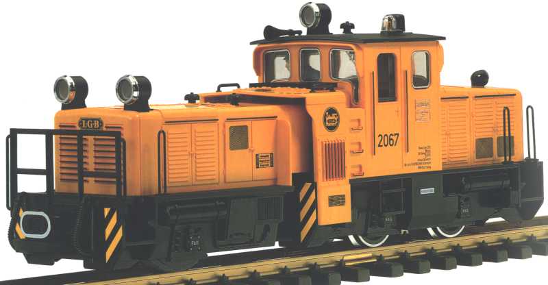
I purchased my 20670 in December 1999 and obtained the version which was designed
to accept the LGB decoder. I wanted to install the ZIMO
MX65S into this locomotive. Therefore, I removed the roof of the cab and also the shell covering the motor. (The detailed steps for disassembly are described later on.) |
 |
I was very happy to find a PCB (printed circuit board) that was almost identical to that in the Brunig steam engine. |
 |
I therefore connected the MX65S decoder in the same manner as for the Brunig engine
and fastened it with some cable ties. This initial conversion took only 30 minutes. The instructions for the 20670 state, in the section about multi-train systems, that the cleaning wheels can be turned on and off using the F1 button on the throttle but that the potentiometer (on the roof) provides no speed control and that the motor always runs at full speed. With the covers still removed, I placed the engine on my test track and everything worked as expected. However, I was not satisfied with this type of operation. The cleaning wheels were turning so fast that I was worried about my track. Whenever the engine stopped, the cleaning wheels would continue to spin, and the direction of the cleaning wheels didn't change with the direction of travel either. This is not at all what I expected! |
|
After this initial conversion, it became pretty obvious how I wanted the engine to function:
To meet the above requirements, it quickly became obvious that I needed a second decoder to implement all these features. In my 'parts box', I found an Itelec 5130 decoder. I don't use this decoder for my engines anymore for two reasons. One, the PWM frequency to drive the motor is too low (MS65S 16 kHz!) and the decoder is too large. However, for use in the 20670, this decoder was perfect ! Using some clever programming of the two decoders, I was able to meet all the requirements I had set for myself as listed above. In the next section I will describe in detail this extensive modification of the 20670. |
|
I installed two decoders into this loco: |
You can of course use other decoders as well. However, since both decoders are controlled by the same address, they must be able to support the same number of speed steps (28 in this case, thus Bit 1 in CV29 set to '1'). Furthermore, it is important that the decoders can handle substantial amounts of current.
The following schematic was used as the basis for my conversion:
| Schematic as PDF file. |
|
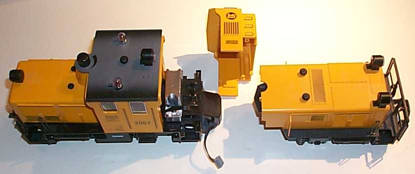 |
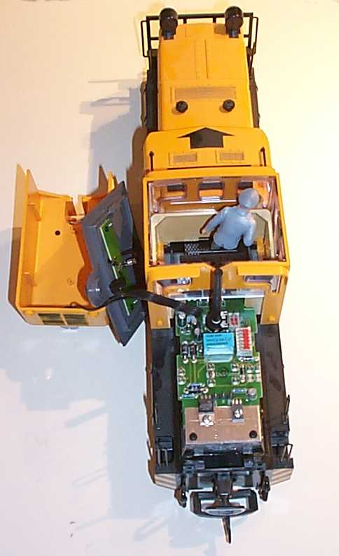
Disassembly of the locomotive is rather time-consuming. First I removed the roof
of the cab (see picture above). Carefully push the sides of the cab outwards to
be able to lift off the roof. Then I loosened the two screws (where I would have
expected two lamps) on the motor housing and removed them. Next I removed the cab. You have to remove four screws on the lower part of the engine, two of which are located in the fuel tanks. Then I removed the small cap next to the main cab (see adjacent photo). To accomplish this, I first had to remove two screws at the bottom which were very difficult to reach with a screwdriver. Now you have to very carefully push apart the sides of the housing and pull the housing up to remove it. Finally I removed the screw connecting the front cleaning section of the locomotive and removed the axle holding the cleaning wheels. Since the LGB PCB is no longer used, I cut all wires as close as possible (important!) at the PCB and removed the PCB from the chassis. |
 |
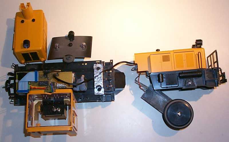
The front cleaning section of the locomotive consists of the black chassis and the yellow hood. I separated these two parts and fastened the Itelec decoder with some double-sided tape inside on the roof of the hood. Then I removed the small PCB, unsoldered the connecting cable for the cleaning wheels and attached these wires to the appropriate track connections of the decoder (refer to the schematic). The connecting cable for the cleaning wheels was attached to the motor outputs of the decoder. |
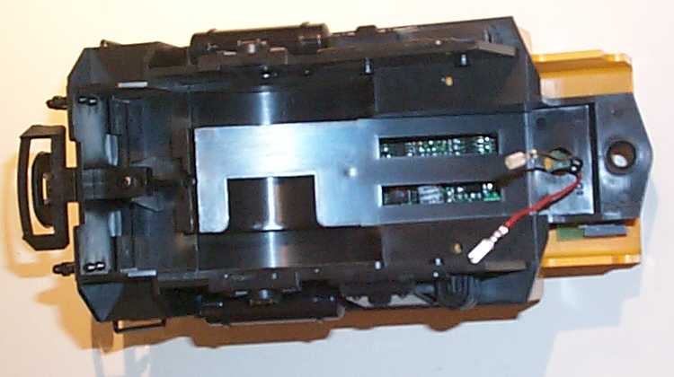 |
The two parts of the front cleaning section can now be re-assembled. The two 5-volt lamps were replaced by 24-volt lamps. The cleaning wheel axle can now be re-assembled into the front cleaning section. |
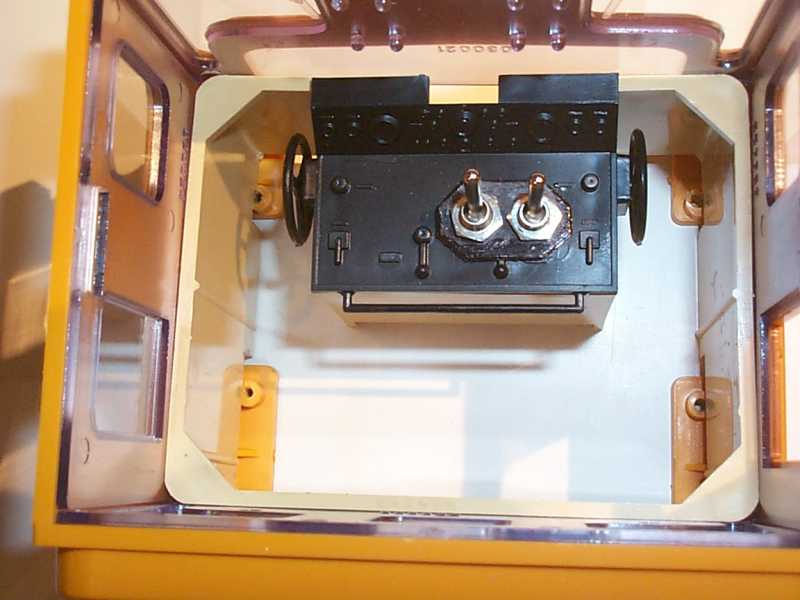 |
To be able to program each of the two decoders individually, one has to be able to connect and disconnect each decoder to and from the track. I attached the two mini rocker switches S1 and S2 (see schematic) inside the cab where the LGB slide switch used to be. |
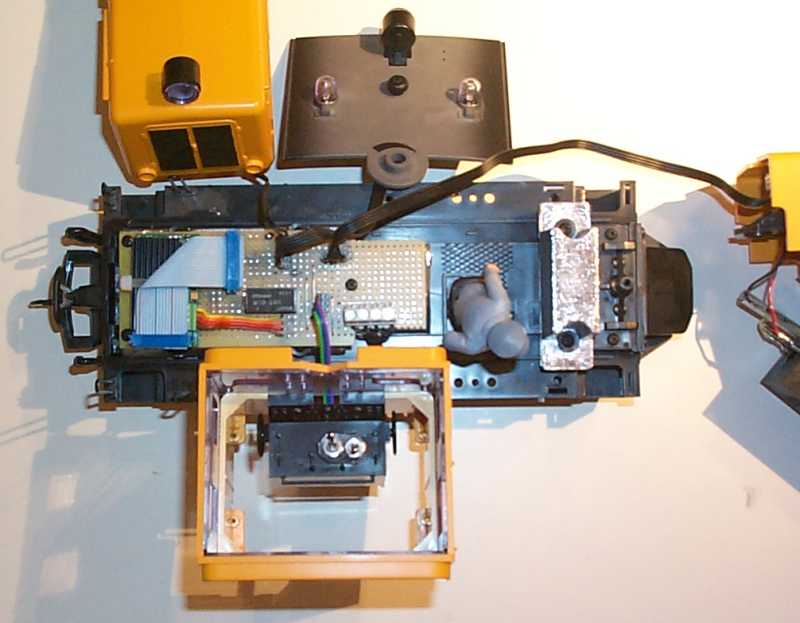 |
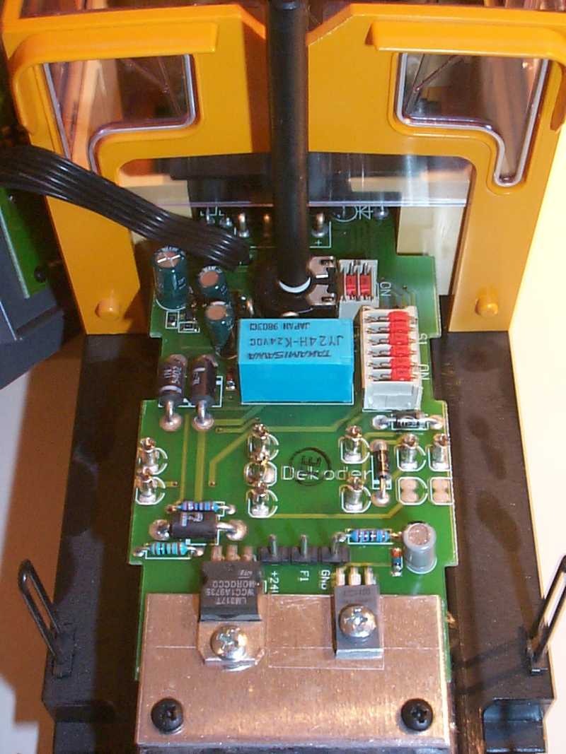
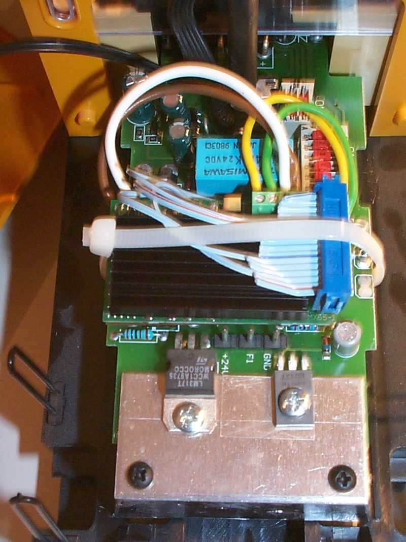
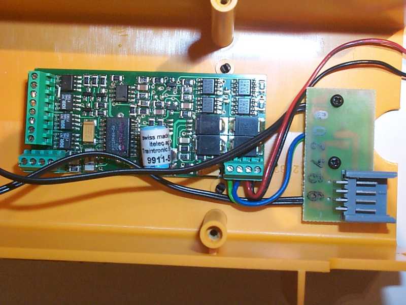
Since this loco has numerous wires, I decided to mount a distribution panel in place of the LGB PCB. The schematic shows this PCB and you can see it in the adjacent photo. To make any future disassembly easier, all of the connections were made using screw terminals or push on connectors. |
 |
The ZIMO decoder was mounted at the front of this PCB using cable ties.
Except for the 24-volt relay and the protection diode, there are no electronics
on this board. When making this board, one has to be careful with the connections
of the various wires in the loco ! Prior to my first test, I replaced all 5-volt lamps with 24-volt ones. The caution lights were given an orange coating using a waterproof felt pen. |
 |
Finally, the big moment. I temporarily connected all parts and initially
switched both S1 and S2 to the OFF position. Then I connected the engine
pick ups to the programming track and switched S1 (ZIMO decoder) to ON.
I programmed this decoder to address '20'. Once this was working, I turned
S1 OFF and S2 ON. The Itelec decoder was also programmed to address '20'. For the next test, I switched S1 ON and S2 OFF, and also connected the track pick ups to the regular track. Now I tried running the loco using address '20'. When all of this was working, I tested the lights. The lights at the front section of the engine and the large light on the roof lit up correctly and changed according to direction. Since the function mapping hadn't been activated yet, I now activated function output 5(caution lights) and function output 6 (cab light). Next I tested the relay. I set the speed to '0' and operated function button 1. One could hear the relay pull in. Finally I tested the cleaning wheel operation. I switched S1 ON and S2 OFF. Now I activated the relay using function F1 and started the loco moving. If everything is connected correctly, the cleaning wheels will now also start to spin. |
 |
After a successful test with the partially disassembled loco, I now carefully
assembled the rest. The best way is to simply reverse the earlier steps for
disassembly. After the final assembly, I tested all of the functions once more
to make sure that all wires had been connected correctly. As a last step, I had to program the two decoders correctly. I started with the ZIMO decoder and switched S1 ON and S2 OFF. To adjust the motor characteristics, I set the CVs as follows (all values are hexadecimal): CV3=x01, CV4=0x01, CV5=0x80 (max. speed), CV9=0x00 (16kHz), CV29=0x02 (28 speed steps), CV56=0x21 and CV58=0xC0. For function mapping: CV33=0x81, CV34=0x82, CV35=0x44 and CV61=0x00. For the programming of the Itelec decoder, I switched S1 OFF and S2 ON I changed the following CVs: CV14=0x88 (F4 not master on/off switch) and CV29=0x02 (28 speed steps). Then I checked to make sure that the cleaning wheels rotate opposite to the driving wheels of the engine. Since this was not the case, I programmed Bit 0 in CV29 to '1' (-> CV29=0x03) and the cleaning wheels now rotated 'correctly'. During my first "Top Speed Tests", I found that the cleaning wheels were simply turning too fast. The Itelec decoder does not have a register to limit the maximum speed (equivalent to CV5 in the MX65S). I therefore programmed a separate speed curve for this decoder and set bit 4 to '1' (-> CV29=0x13). Using speed curve programming, one can now adjust the speed (RPM) of the cleaning wheels to suit ones requirements. I finally switched S1 ON and S2 OFF, now the locomotive was ready for use. |
This conversion took the better part of a day and I was really pleased at the end when everything was working as expected. The only annoyance is that the caution lights on the roof are now simply lit when in the cleaning mode, they should be flashing. Maybe later.... ?
I can now control my track cleaning loco using address (20) and activate the cleaning wheels using F1. When I stop the locomotive, the cleaning wheels stop automatically, and I can clean in both directions.
TopTranslated by Knut Schartmann