
All modifications described herein are done at your own risk !
| Home Garden Railway Digital Conversions | |
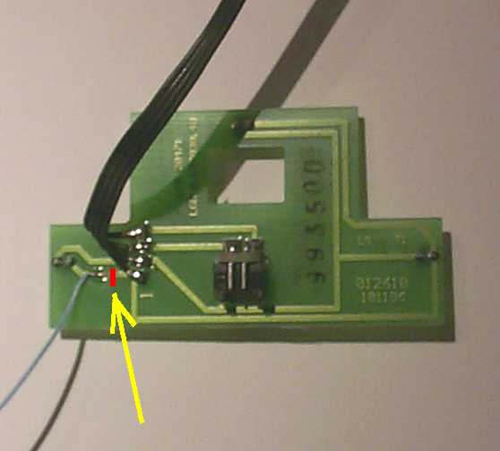
I equipped this loco with the ZIMO MX65S decoder. I did not want to change the 5 volt lights and the smoke generator and wired the decoder directly to the LGB PCB (printed circuit board). The following diagrams show the LGB PCB and the connections for the ZIMO decoder.
The pins marked in red are actually meant for direct connection of the 55020 LGB decoder. I proceeded as follows with my conversion:
The following must be noted:
Unfortunately, on this loco, only the lights in the direction of travel are illuminated; the taillights are not. I have connected the appropriate lights to the light in the cab as follows:
At present, only Semaphore in Switzerland offers a sound module for this locomotive. The price for the sound module kit was SFr 565.00 (as of 26.Jan.2000). Since I found this too expensive, I opted for a compromise with respect to absolute true prototype sound and decided to use the Soundtraxx DSX sound module " British L-1 Class tank ". This is a digital decoder which only provides sound and is connected in parallel to an existing decoder (in this case ZIMO MX65S). I purchased this module directly in the United States (see homepage Soundtraxx) for approx.. SFr. 250,00 (postage and handling included). You can listen to samples of the various sounds on Soundtraxx's homepage.
Connecting this decoder is very simple:
The ZIMO MX65S decoder and the Soundtraxx decoder are programmed to respond to the same address. That way, one can select the locomotive, control it as required and also have full control of the sound functions of the sound decoder. To be able to program each decoders separately, a small on/off switch needs to be installed for each of the decoders.
The one problem that still remains is synchronization of the "steam exhaust chuff" with the speed of the locomotive. One option is to use the Soundtraxx "Auto-Exhaust" feature of the decoder. In this mode, the decoder generates the 'exhaust chuff' based on the speed control setting of the throttle. Unfortunately, during rapid changes in speed, the 'chuff' synchronization no longer works satisfactorily.
In the above diagram, a "Cam Pickup" wire is shown. If one connects this wire with one of the two rails, a "chuff" sound is generated. I therefore decided to use a reed contact and magnet to generate the "chuff" sounds. If one removes the lower cover of the locomotive, one will find that the perfect space for a 'magnet-wheel' exists near the very first axle.
I made a plastic disc, 20mm (3/4 inch) in diameter and 8mm (1/4 inch) in thickness. Then I filed slots for the four round magnets (diameter 2mm, or 1/16th inch) and fastened them with quick-setting adhesive. One has to be careful that all the positive and negative poles of the magnets are facing the same side of the plastic disc. I then cut a segment out of the disk, pushed the disc onto the axle of the locomotive and fastened it with quick-setting adhesive as well. I re-attached the segment. Next I mounted the reed switch. It is advisable to check that the reed switch is actually triggered by the magnets (use a continuity tester or a multimeter).
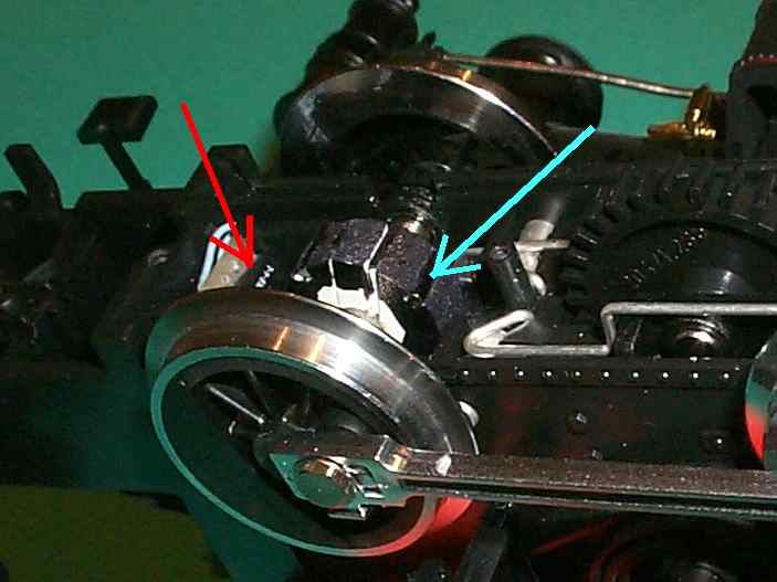
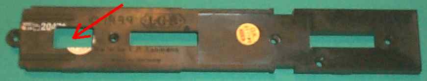
The red arrow points to the reed switch. The blue arrow points to one magnet on the disk. One has to make an opening in the base plate to accommodate the disc (red arrow).
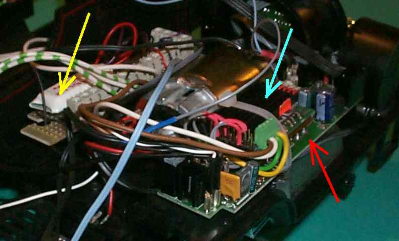
The next illustration shows the ZIMO decoder (blue arrow), the sound decoder (yellow arrow) and the original LGB PCB (red arrow).
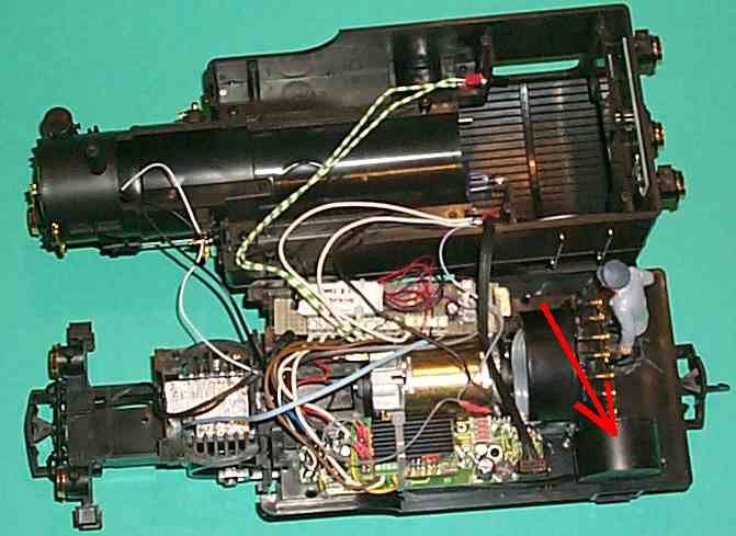
The loudspeaker (red arrow) was placed in the corner of the cab
Translated by Knut Schartmann