
Use of the information described herein is done at your own risk !
| Home Garten Railway Digital | |
| ! Important Advice ! |
|
In the past, I encapsulated my MX81 decoders using silicon so that I could use them outdoors.
Unfortunately, now two of the three MX81 decoders are no longer operational. I therefore now use a special casting method and the four MX81 decoders encapsulated this way have been working without any problems for the last six month. |
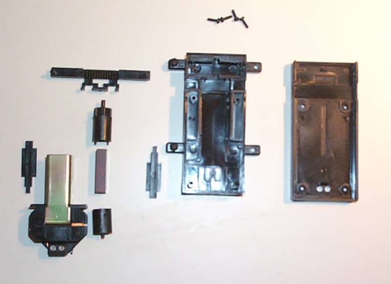 |
To start with, I disassembled the complete EPL switch drive into its individual components. |
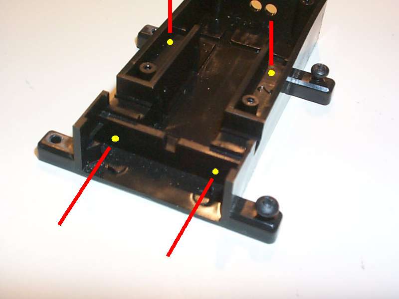 |
Using a 2mm (3/32 in) drill bit, I drilled a total of four holes at the points marked in yellow. |
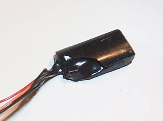 |
I then used a special two-part casting material (Astorit 903S) to encapsulate the decoder. The biggest problem is to construct a good casting form and then to pour the material without any air bubbles. |
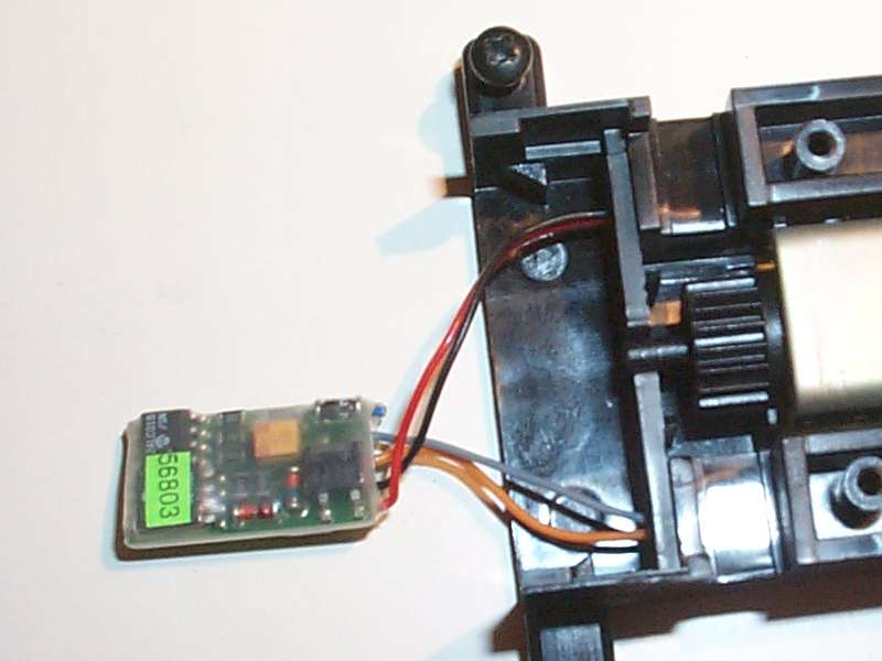 |
The decoder then slips into the cavity which normally houses the auxiliary switch. This switch of course can now no longer be used. I cut off the blue wire close to the decoder since it is not used. The other wires "black", "gray", "red" and "orange" were fed through the appropriate holes. These wires were kept at their original length ! |
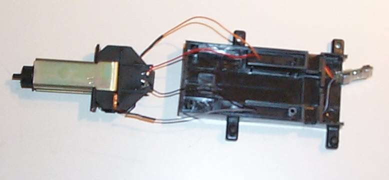 |
I removed the two wires between the coil and the connecting block. and soldered wires "black" and "red" to the connecting block. The "gray" and "orange" wires were soldered to the wires of the coil. Heat-shrink tubing was used to insulate the solder connections. |
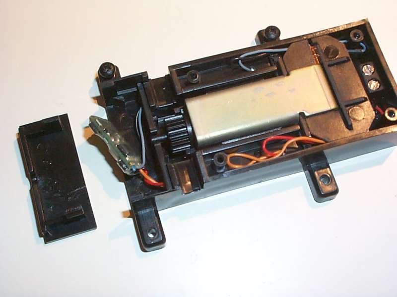 |
The two small plastic pieces are then placed to the right and left of the motor and the motor is then placed into
the housing. Make sure that none of the wires are pinched anywhere. The corner has to be cut off on both sides of
the plastic vertical motor enclosure so that the wires can pass. The wires are folded back on the right and left
side of the switch drive. That way, one can lift out the switch drive later for cleaning. On the switch activation rod, I removed the guides for the auxiliary contacts. To position the activation rod correctly, it is best to turn the motor so that the small cam is perfectly vertical, pointing up. You now position the activation rod exactly centrally. To prevent moisture from entering through the two holes in the housing, I sealed these with Araldit. This means however that the cover now has to be removed to connect the cables. |
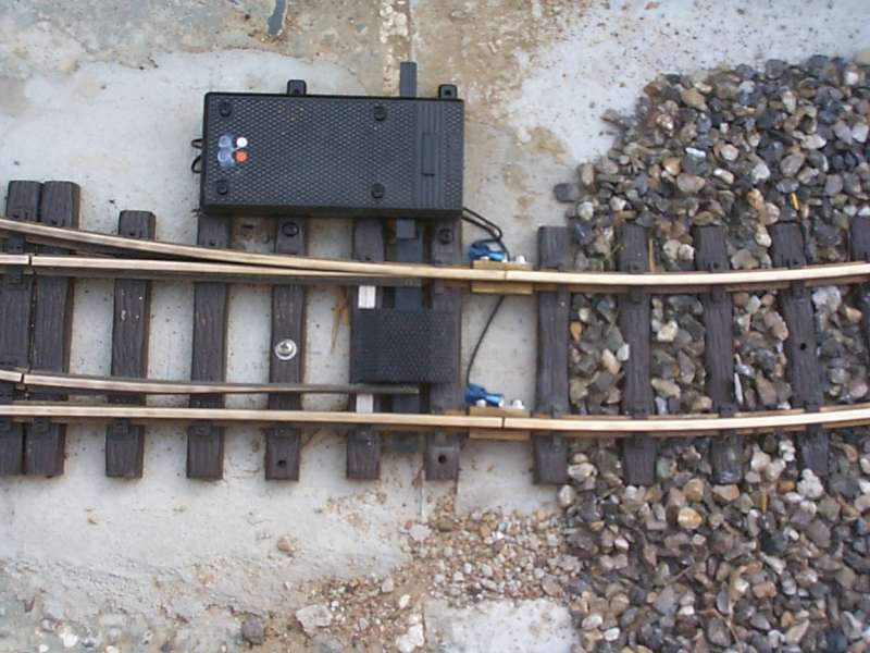 |
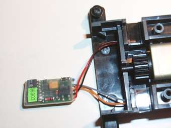
The picture at the left shows a digitized EPL-Drive completely installed and wired. However, before the decoder is installed, it has to be programmed. |
 |
To program the MX81N, connect it to the DCC command station (in this case Chief by Digitrax) following the
schematic drawing on the left. Using the "Chief", the MX81N can be programmed using the "dir" mode (direct CV programming), just like a regular mobile decoder. CVs (Configuration Variables) or registers can therefore be read. The most important registers are explained in more detail in the following tables. |
| The MX81N decoder can also be connected to a Lenz systen, Lenz LZ100/LH100 (Software V 2.3), using the same schematic. Programming however is only possible using a "trick". Uwe Nehls has investigated this in great detail and the following is his information to work around the issue. | |
| Problem: | After selection of the programming mode (F8, Enter, Enter), the central station automatically switches into the Reg-mode. Cause unknown. |
| Consequence: | Higher numbered registers (REG>R8) cannot be selected. |
| Solution: | Select the program mode without (!) having the decoder connected, Chose the CV-mode (+/- buttons); after some time, the LH100 will display the error message ERR02; cancel this using the CL-button (and only the CL-button!); connect decoder; now you can read in the CV-mode and also program. |
|
In the following tables, I use the numbering scheme 0...7 for the bits. Some DCC manufacturers such as Lenz, use a
numbering scheme from 1...8. In those cases, one has to add 1 to the bit numbering. According to the Zimo manual, the registers (CV numbers) for the MX81N start at number 513. Many DCC systems do not support access to these high register addresses. Therefore I have shown the "lower" register addresses in the tables. To use the higher addresses, just add 512 in each case. |
| Register (CV) | Designation | Notes |
| 1 | Address | Bit 0..7 (See the next table for an explanation) |
| 9 | Address | Bit 8..9 (See the next table for an explanation) |
| 33 | Subaddress | Werte 0..3 (See the next table for an explanation) |
| 3 | Switching pulse duration for sub address 0 | Default value "2" means 0.2 seconds and this should be used for EPL-drives. |
| 4 | Switching pulse duration for sub address 1 | Refer to register 3 |
| 5 | Switching pulse duration for sub address 2 | Refer to register 3 |
| 6 | Switching pulse duration for sub address 3 | Refer to register 3 |
| 38 | Bit 0: Recognition of switch position Bit 1: Select switch drive polarity |
"0" = deactivate the recognition of switch position "0/1" = Change switch drive polarity |
| The complete description of all registers is listed in the user manual of the MX81N decoder. This manual is available for download in pdf format (using Adobe Acrobat reader) at the homepage of ZIMO. |
| The ZIMO addressing arrangement uses the concept of a primary address and a sub address. If the MX81N is to be used with another DCC system, the addressing must be modified per the following table: |
| Digital-Address (Digitrax,Lenz) |
Primary address of the MX81N CV 1 Bit 0..7 |
Primary address of the MX81N CV 9 Bit 8..9 |
Sub address of the MX81N CV 33 |
| 1 | 1 | 0 | 0 |
| 2 | 1 | 0 | 1 |
| 3 | 1 | 0 | 2 |
| 4 | 1 | 0 | 3 |
| 5 | 2 | 0 | 0 |
| 6 | 2 | 0 | 1 |
| 7 | 2 | 0 | 2 |
| 8 | 2 | 0 | 3 |
| 9 | 3 | 0 | 0 |
| ... | ... | ... | ... |
| 26 | 7 | 0 | 1 |
| ... | ... | ... | ... |
| 550 | 138 | 0 | 1 |
| Another option is to calculate the digital address as follows: |
| Primary address = ((Digital address - 1) DIV 4) + 1 |
| Sub address = (Digital address - 1) MOD 4 |
| "DIV" means integer division, "MOD" means remainder left after the the division. Therefore, the result of [9 DIV 4] is "2" and the result of [9 MOD 4] is "1". |
|
When installing the modified switch drive and wiring the MX81, one needs to determine if the switch drive
is to be connected at the right or the left of the switch and if this is to become a right-hand or
left-hand switch. The official manual of the MX81 provides no information how the polarity of the switch
drive can be reprogrammed later on. I then received a tip that bit 1 in CV 38 can be used for just that (see above table). Thus, should the switch operate the wrong way, one can simply change this bit from "0" to "1" or vice versa. The best approach is to test the drive with the programming track prior to final installation. Once installed, reprogramming is no longer possible. |
 |
For normal operation, connect the MX81N decoder to the DCC system via the track using the schematic information
on the left. Programming for any system other than Zimo should be done per the information in the above tables. During normal use, it has been noted that the MX81N decoder will shut down for safety reasons (heat), if it is operated quickly in succession a number of times. One then has to wait several seconds until the MX81N can operate the switch motor again. |