
All modifications described herein are done at your own risk !
| Home Garden Railway Digital Conversions | |
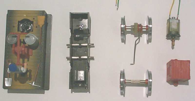 |
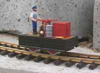
The disassembly of the 20010 is relatively simple. First, I removed the red crate
on the hand trolley (2 screws). The motor can be now pulled out. I then carefully
pulled off the two motor terminals using needle-nose pliers. Next, I loosened the two screws at the bottom and carefully removed the lower shell. I also removed the two axles. A small PCB (printed circuit board) is snapped onto the 4 current collectors. I removed this PCB to mount the decoder on it. |
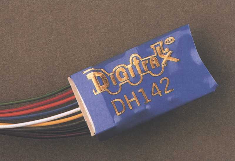 |
The decoder I used for the hand trolley is the Digitrax DH142. It can handle 1.5A of current in continuous operation and has back-emf load compensation. The design is compact and the cables are connected directly to the decoder via a special plug. |
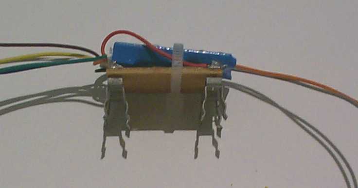 |
I fastened the decoder directly onto the PCB of the current pick-ups using a small cable strap. The two wires for the track connection were soldered directly to the PCB. |
 |
The assembly takes place in the reverse order of the original disassembly. I soldered
the two motor connectors to the appropriate wires of the decoder. During programming of the decoder, I changed some of the CVs which control the back-emf load compensation (CV55 = 0x30, CV56 = 0x20, CV57 = 0x03, all Hex values!!). With these values the handcar starts reliably and runs at medium speed quite steadily. Unfortunately, at the lower speed range it's jerky, but this problem is caused mainly by the lever mechanism |
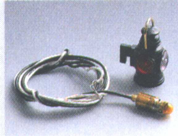 |
Due to the short wheel base and the low weight of the handcar, I constantly had the problem that the trolley would not start running. I though that a small lantern would be useful, since one could see immediately whether the hand trolley had power or not. In my LGB parts box, I found a US caboose lantern (68332). Not exactly prototypical, I know! The bulb mounts into a small socket and the lantern fits on top. |
 |
I drilled a hole (diameter of the bulb socket) exactly in the center between the
axles in the floor of the hand trolley. I inserted the socket into this hole and
fastened it from below with two-component epoxy (Must be able to fasten brass to
plastic and tolerate some heat). In order to determine the exact height of the
socket, I mounted the lantern and waited for the epoxy to dry. I routed the
two wires to the inside of the hand trolley, where one has to make a hole in one
side and a recess in the other side. I connected the lamp directly to the
function output "light front" of the decoder. Then I programmed CV61 to the
value 0x01 (Hex). This setting causes the "light front" function output "F0"
to be controlled by the function button only and makes the lamp independent of
the direction of travel of the handcar.
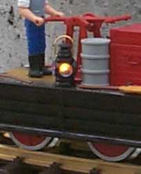
With the lamp on the hand trolley, I now know immediately if the vehicle even has power or not. |
Translated by Knut Schartmann